13. Network
Reflection
Group Assignment
Attached is the link to group assignment
Individual Assignment
0. Instructors Suggestions
Please fix:explain briefly the networking/communications protocol(s) and how it works in your arduino r4 wifi + esp32c3 example -- Added in green
for project 2 (websocket), explain briefly what the project does & how it works -- Added in green
Learning from Interfacing and Networking
Through this project, I have learned the intricacies of Serial and TWI communications. Serial communication was pivotal for interfacing with the computer for debugging purposes, while TWI enabled direct MCU-to-MCU interaction. Below is a table summarizing the key commands and concepts:
| Concept | Description | Key Commands |
|---|---|---|
| Serial Communication | Enables data transfer between the MCU and a computer or other serial devices. | Serial.begin(115200);Serial.println("message"); |
| Serial Data Handling | Reading incoming serial data from the computer. | if (Serial.available())char c = Serial.read(); |
| TWI/I2C Communication | Multi-master, multi-slave, packet-switched communication protocol. | Wire.begin(); (master)Wire.begin(address); (slave) |
| I2C Data Transmission | Sending and receiving data packets between MCUs. | Wire.write(byte); (send)Wire.read(); (receive) |
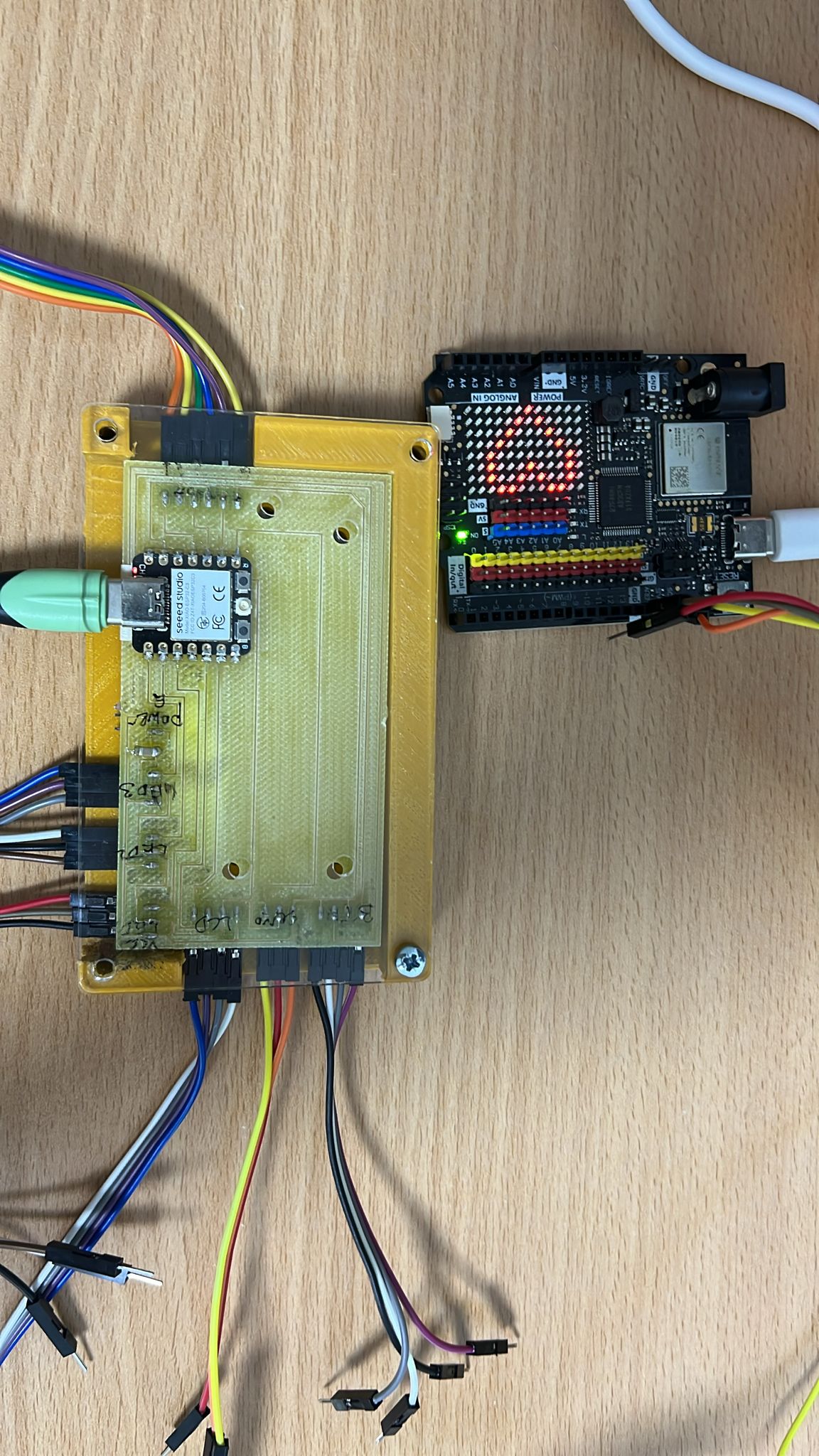
Design and Fabrication
I took time to learn how to programme UNo Wifi R4 inbuilt LCD display so I started with reading its datasheet.
Then tried the tutorials. with picture shown below.
Next I connected the R4 to esp32 via twi setup. Where SCL is connected to SCL and SDA to SDA and both sharing common ground. I wanted to make it such that when 1 is kkeyed into my computer, it will show a certain image. and 0 another image.
Programming Approach
The development of the project's codebase was iterative. I started with simple blink tests and gradually integrated the communication protocols. My strategy was to write modular code, enabling easy testing and debugging of individual components before bringing them together into a cohesive program.
Source Code and Design Files Shown
For R4
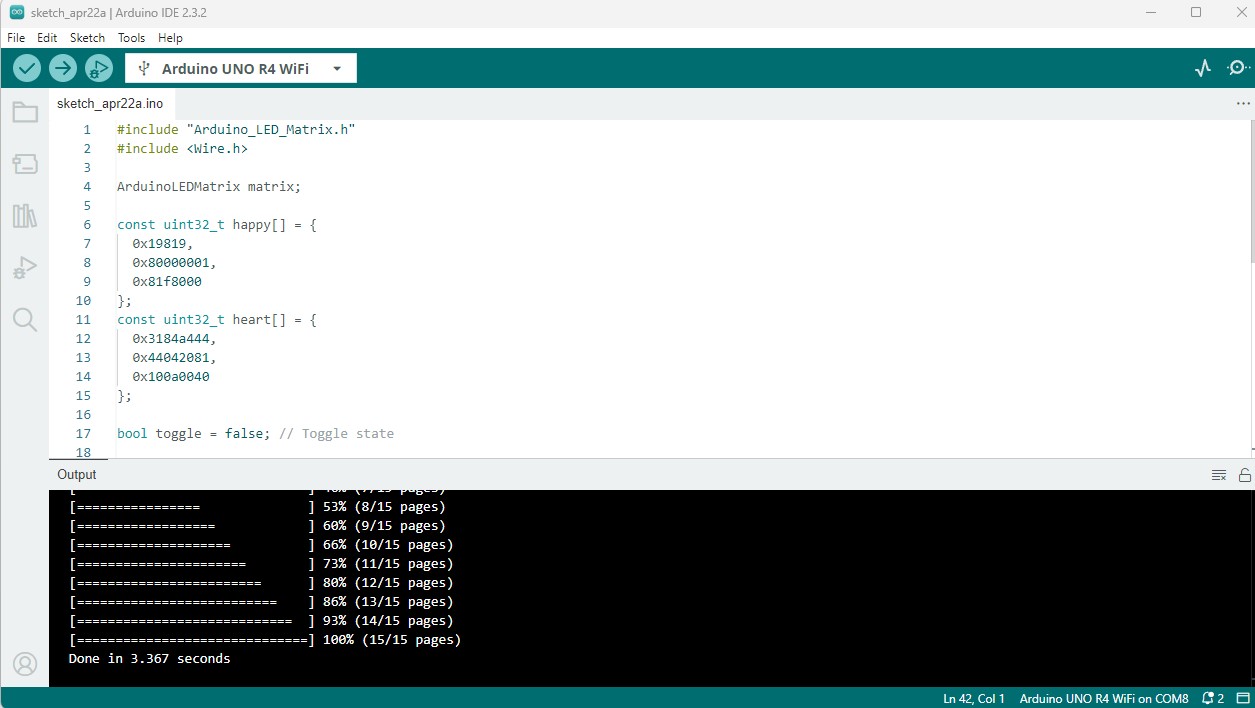
    #include "Arduino_LED_Matrix.h"
    #include

    ArduinoLEDMatrix matrix;

    const uint32_t happy[] = {
      0x19819,
      0x80000001,
      0x81f8000
    };
    const uint32_t heart[] = {
      0x3184a444,
      0x44042081,
      0x100a0040
    };

    bool toggle = false; // Toggle state

    void setup() {
      Serial.begin(115200);
      matrix.begin();

      Wire.begin(4); // Set up I2C on address 4
      Wire.onReceive(receiveEvent); // Register I2C receive event
    }

    void loop() {
      if (toggle) {
        matrix.loadFrame(happy);
      } else {
        matrix.loadFrame(heart);
      }
      delay(500); // Delay for visibility
    }

    void receiveEvent(int bytes) {
      while(Wire.available()) { // loop through all but the last
        byte x = Wire.read(); // receive byte as a character
      }
      toggle = !toggle; // Toggle the display on each signal received
    }
For Esp32
    #include

        #define I2C_ADDRESS 4 // I2C address of the UNO R4 WiFi

        void setup() {
          Serial.begin(115200); // Start the serial communication
          Wire.begin(); // Join I2C bus as master
          Serial.println("Send '1' to toggle UNO R4 WiFi LED display.");
        }

        void loop() {
          if (Serial.available()) { // Check if data is available to read
            char c = Serial.read(); // Read the incoming character
            if (c == '1') {
              Wire.beginTransmission(I2C_ADDRESS); // Start transmission to device
              Wire.write(1); // Send the toggle command, value '1'
              Wire.endTransmission(); // End transmission
              Serial.println("Toggle command sent.");
            }
          }
          delay(10); // Small delay to prevent flooding
        }
Brief Description of Project
I use the I2C (Inter-Integrated Circuit) communication protocol to set up communication between an Arduino UNO R4 WiFi and an ESP32.
I2C is a synchronous, multi-master, multi-slave communication bus that operates using two lines: SDA (Serial Data Line) and SCL (Serial Clock Line).
The master device (ESP32) initiates(via wire.begin() and wire.write()) and controls the communication (Wire.beginTransmission(I2C_ADDRESS)), while the slave device (Arduino) responds (Wire.onReceive(receiveEvent);).
For the Arduino UNO R4 WiFi setup, I included the necessary libraries by adding #include
In the setup() function, I initialize the I2C interface as a slave with the address 4 using Wire.begin(4);.
I defined the receiveEvent() function to handle incoming data by toggling a boolean variable(toggle) that switches between display states.
With Wire.onReceive(receiveEvent); I ensure, the function gets called when data is received.
The Arduino will toggle its display state upon receiving the byte, alternating between two predefined frames on the LED matrix.
For the ESP32 setup, I also included the Wire.h library and initialize the I2C interface as a master in the setup() function with Wire.begin();.
I check for serial input from the user. When '1' is received, I initiate an I2C transmission to the Arduino with Wire.beginTransmission(4);,
send a byte using Wire.write(1) and then I end the transmission with Wire.endTransmission();.
Updated Original Design Files and Source Code
- Source Code for First I2C Project Zip - Source Code for Website and ESP32 - Source Code for ATTINY1614 Old Project Zip - ESP32C3 Board Designed
Project 'Hero Shot'
In the video, you can see that when i type in 1 into my serial prompt, it will change the display.
v3 Project 2: Instructor Request for Website to control esp32 instead of using twi only
instructor requested me to redo the assignment so that I can use website to control the esp32.
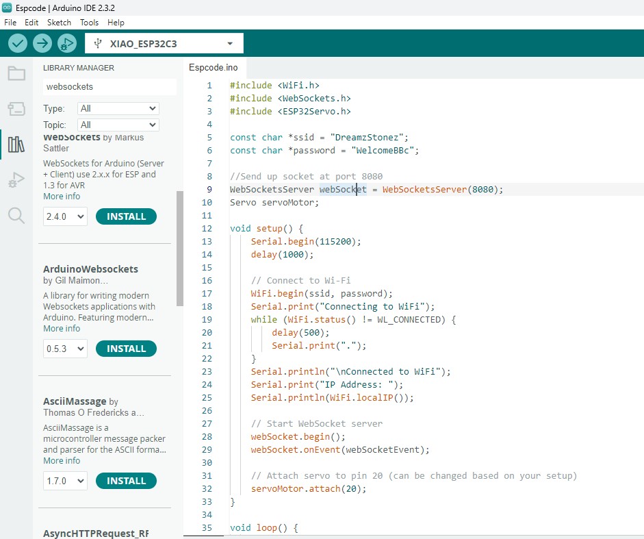
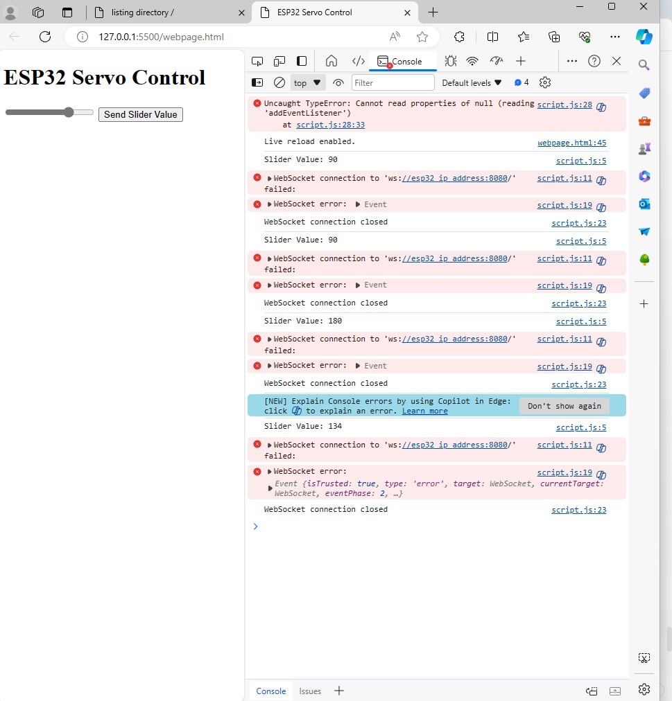
So I started writing the html where I have a slider and button. then I wrote the JS to listen to slider and button clicks. then i used websocket to send data to the wifi address from my esp32.
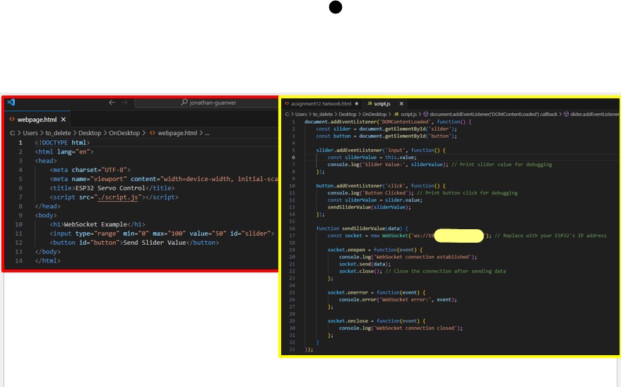
Next I started to install the libraries needed in my arduino ide and uploaded my arduino code and upload code to esp32 check my wifi ip address.
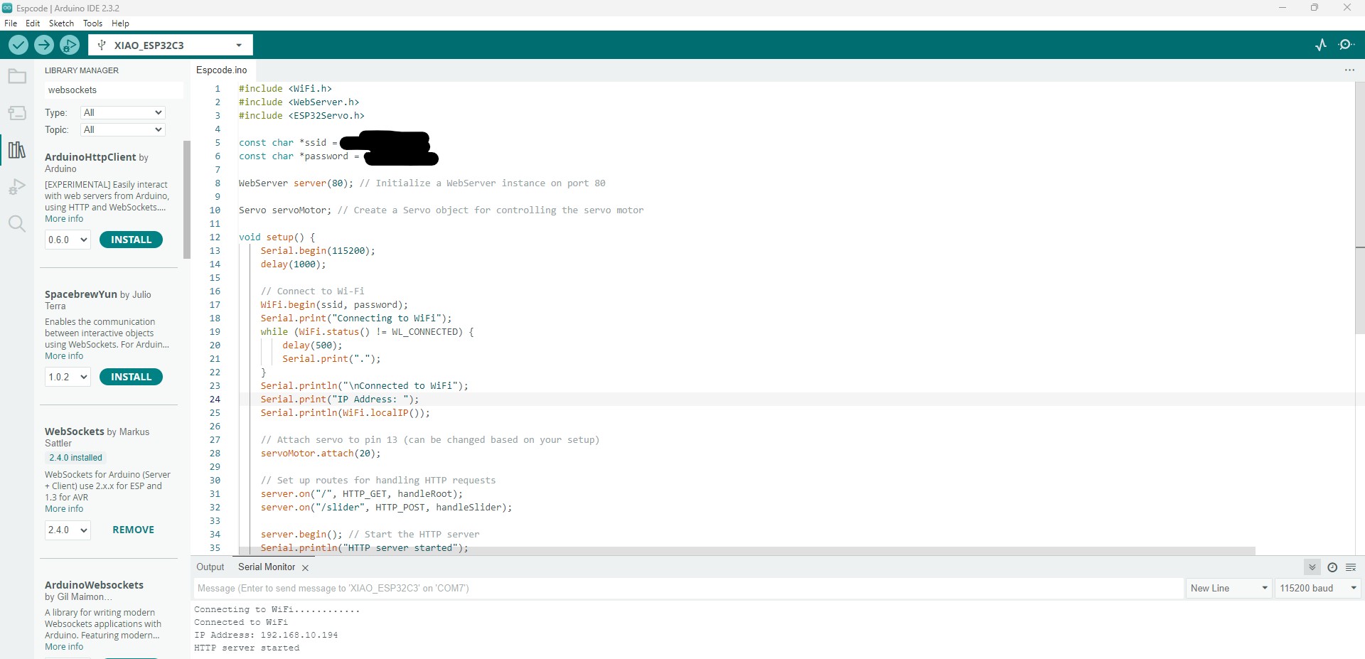
Next I start to test the buttons and sliders with my browser and ensure my devices connect to same wifi and ip address are correct.
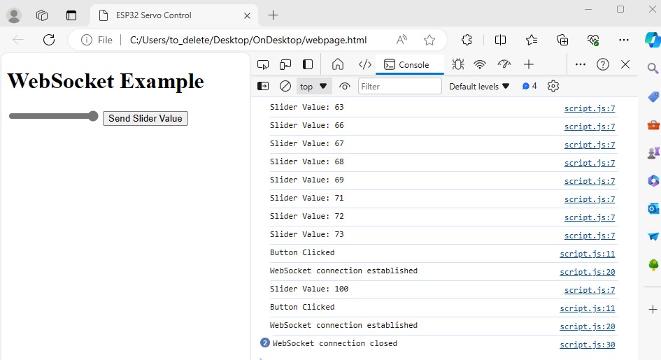
Brief Description of Static Website and ESP32
I set up a web interface with a slider and a button using HTML and interactivity via js.
I allows a user to control a servo motor connected to an ESP32 microcontroller.
When the page loads, the JavaScript listens for changes in the slider's position and logs the value.
When the button is clicked, the current slider value is sent to the ESP32 using a WebSocket connection.
WebSockets provide a full-duplex communication channel (thats the technical term, the easier word is two way communication simultaneously.) over a single, long-lived connection (this also just a fancy term to mean the connection is constantly in use without need to connect and terminate multiple times), which is more efficient than traditional HTTP requests(which needs multiple handshakes) for real-time data transfer.
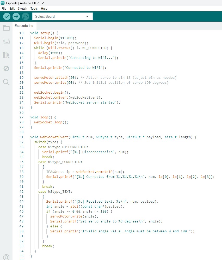
The ESP32 code initializes a WiFi connection using the provided SSID and password(which is wifi name and password in normal layman), and then sets up a WebSocket server(this server is the reason why it have 2 way and long lived connection) on port 8080.
It also initializes the servo motor. The loop function keeps the WebSocket server running, listening for incoming connections. When a message is received, it obtains the servo angle and use it to adjust the servo motor's position. This allows for real-time control of the servo motor based on the slider's position in the web interface. Though it is real time, it actually lags by a few seconds maybe due to my network.
Encountered Problems and Solutions
Took some time to understand the const uint32_t happy[] = {
0x19819,
0x80000001,
0x81f8000
};.
Found articles explaining that In hexadecimal, each digit represents 4 bits. Therefore, each uint32_t can represent up to 32 bits. In the context of an LED matrix, each bit corresponds to the state of an individual LED: a 1 and 0 is used to control state.
I previously also had programmed and document how I used an ATTINY1614 which I designed and made it communicate with arduino, where when my ATTINY1614 is pressed, it will light up and also send signal to arduino and arduino will send signal to PC same via TWI, but as I did not use my own milled programmer, I redo it now using ESP32. Hope this ESP32 version suffices!